Single element
![]()
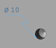
This function allows you to create a dimension from a selected element or from two selected points. The possible types of dimension depend on the selected element (segment or circle).
Access
- Click the
 icon in the Annotations tab.
Or
- Type "Element" in the Quick Search field and then press Enter.
Procedure
- Select the appropriate Environments and Filters options.
- Select the reference element/points in the graphic area:
- Select the type of dimension in the Filters section of the Options tab, or by using keyboard shortcuts:
- Diameter
 : This option allows you to add a diameter symbol to the dimension value.
 - Inside witness lines
 : This option allows you to force the dimension value to remain inside the witness line.
 - Int. line On
 : This option allows you to deactivate the arc display of the dimension. It also activates the Outside arrows option.
 - Move text
 : This option allows you to pick the position of the text on the angular dimension. When activated, the text dynamically follows the mouse cursor. Click to validate text and angular dimension position.
 - Outside arrows
 : This option allows you to add outside arrows to the angular dimension.
 - Internal arrow
 : This option allows you to add an internal arrow to the angular dimension.
 - Parallel reference
 : This option allows you to force the dimension to be parallel to a reference element (solid, segment, line, etc.).
 - Perpendicular
 : This option allows you to force the dimension to be perpendicular to a reference element (solid, segment, line, etc.).
 - Incline dimension
 : This option allows you to incline the dimension.
 - Direct
 : This option allows you to align the dimension to the selected segment.
 - Horizontal
 : This option allows you to force the dimension to be horizontal with respect to the current workplane.
 - Vertical
 : This option allows you to force the dimension to be vertical with respect to the current workplane.
 - Radial
 : This option allows you to add the radius dimension when you have selected a circle.
 - Diametral
 : This option allows you to force the diameter dimension text when you have selected the Radial option.
 - Cross
 : This option allows positioning of the dimension inside the selected circle.
 - Internal leader
 : This option allows you to make the leader point pass through the selected circle.
 - Extend arc
 : This option allows you to make the leader extend the selected arc.
 - Horizontal
 : This option allows you to draw a horizontal leader when you have selected the Radial option.
 - Zig-Zag
 : This option allows you to draw a zig-zag leader when you have selected the Radial option. You cannot draw an Internal leader with this option.
 - Press the [T] key or click the
 Properties icon. This allows you to enter and configure text after validation.
 - Enter your text and define parameters (See Dimension Properties).
- Click Apply to validate and close the dialog box.
- Click a point to position the angular dimension.
Dimension with outside arrows and moved text:

Circle dimension with Radial, Diametral, Horizontal and Zig-Zag options activated:
Keyboard Shortcuts
- [M]: Dynamically define the text position using the mouse.
- [D]: Draw the diameter (and/or the Feature string if it exists for the radial dimension).
- [P]: Force the dimension to be parallel to the reference element.
- [A]: Switch between inside/outside arrows.
- [C]: Change the selected point of the annotation rather than shorten the gap between the end of the witness line and the picked point (only for linear dimension).
- [W]: Switch between the three workplanes.
- Space bar: Position the text to the standard positions of the dimension.
- [Ctrl] + Enter: Edit the selected dimension.
Dimension Properties
General Values Tab

|
Remember settings |
Activate this option to save your current settings. |
|
Text field |
Enter/Modify the text in this field. You can use keyboard shortcuts to add special characters:
|
|
Height |
Enter the height of characters in this field. |
|
Width |
Enter the width of characters in this field (only for static text). It is disabled if the Static proportional text option is activated. |
|
Char gap |
Enter the distance between each character in this field. It is disabled if the Static proportional text option is activated. |
|
Gap under text |
Enter the distance between the lines in this field. |
|
Local scale |
Enter a new text scale in this field. |
|
Select font |
Click this button to define the font parameters. |
|
Static proportional text |
When this option is activated, proportional text is applied; the width of characters is calculated as a ratio relative to the height of characters. |
|
Text attribute |
Select the text attribute in this drop-down list: Underline, Overline, etc. |
|
Trailing places |
Select whether you want to display (Yes) the insignificant zeros following the decimal places or not (No). |
|
Separator |
Activate this option to draw a point after the integer when there are no trailing places. |
|
Leading places |
Activate this option to display all of the insignificant zeros which precede the decimal place. |
|
Trim crossing lines |
Click this button to trim the dimension witness line when it crosses another dimension line. A confirmation message is displayed. |
|
Draw Symbol |
When you select entities with CAM attributes, you can generate a leader dimension with the CAM values (e.g. Diam. 8 Rough Boring or M12) by activating one of the following options:
|
|
Update features |
Click this button to apply description strings from the Feature Manager. |
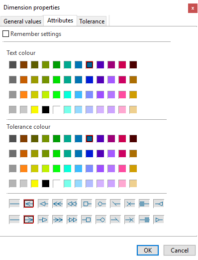
Attributes Tab
|
Remember settings |
Activate this option to save your current settings. |
|
Text colour |
Select the text colour. |
|
Tolerance colour |
Select the tolerance colour (See Tolerance Tab). |
|
Arrow style |
Select the arrow style for both sides of the arc. |
Tolerance Tab

|
Remember settings |
Activate this option to save your current settings. |
|
Add Tolerance String |
Activate this option to display the tolerance settings. Select the tolerance settings from the drop-down list below the option. |
|
Tolerance on |
Activate this option to insert tolerance text after the dimension value. |
|
Sup. tolerance |
This field indicates the upper tolerance value. The value depends on the tolerance settings selected in the Add Tolerance String drop-down list. |
|
Inf. tolerance |
This field indicates the lower tolerance value. The value depends on the tolerance settings selected in the Add Tolerance String drop-down list. |
|
Tolerance dual value |
Activate this option to display the upper and lower tolerance values between brackets after the dimension value. |
|
Double dimension |
Activate this option to display the dimension value in both mm and inches. |
|
Decimal places |
Enter the number of decimal values in this field. |
|
Trailing places |
Activate this option to display the insignificant zeros following the decimal places. |
|
Leading places |
Activate this option to display all of the insignificant zeros which precede the decimal place. |
|
Tolerance position |
Select whether to position the upper and lower tolerance value level with the Bottom of the dimension value or with the Middle of the dimension value. |
|
Before |
Enter the text to be added before the dimension in this field. This option allows you to select predefined text in the application:
|
|
After |
Enter the text to be added after the dimension in this field. This option allows you to select predefined text in the application:
|
Editing Existing Dimensions
Editing the Dimension Position and Type
- Run the Single element command.
- Select the corresponding dimension.
- Click one of the points on the dimension.
- If necessary, modify the type of dimension.
- Click another point to change the dimension position.

|
|
Editing the Angular Dimension Properties
- Run the Single element command.
- Select the corresponding angular dimension.
- Press the [T] key or click the Properties icon.
- Modify the angular dimension properties (See Dimension Properties).
- Click Apply to validate and close the dialog box.